What Is a Butter Valve and How Does It Work?
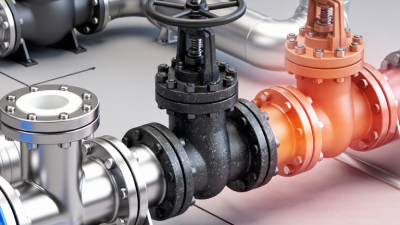
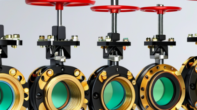
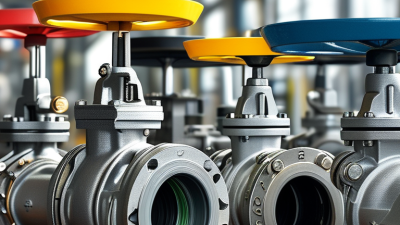
A Butter Valve, more commonly called a butterfly valve, regulates fluid flow with a circular disc mounted on a rotating shaft. When the shaft turns ninety degrees, the disc moves from fully open to fully closed. The mechanism is simple, compact, and easy to recognize: a thin metal disc sits inside the pipe, like a door turning on its edge.
This design serves water treatment, HVAC systems, chemical processing, food production, and fire protection. Industry reports from Grand View Research and Mordor Intelligence place the global butterfly valve market in the multi-billion-dollar range, with steady mid-single-digit growth expected in coming years. Their findings reflect rising investment in municipal pipelines, industrial automation, and energy infrastructure. The figures vary between reports, however. That difference deserves attention before using market data for business decisions.
Philip L. Skousen, author of Valve Handbook, describes the basic purpose clearly: “A valve is a mechanical device that controls the flow of fluids.” His statement remains useful here. A Butter Valve does not merely stop flow; it can also throttle flow when properly selected and controlled. Yet throttling creates turbulence, pressure loss, and possible seat wear. This is where practical engineering matters.
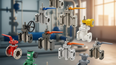
Selection depends on pressure class, temperature, media compatibility, body material, disc design, and actuation method. API 609, AWWA C504, and EN 593 provide important reference points. Still, standards cannot replace field judgment. A valve that performs well in clean water may fail quickly in abrasive slurry. Understanding how the disc, stem, seat, and actuator work together is essential.
Definition and Basic Purpose of a Butter Valve
What Is a Butter Valve and How Does It Work?
“Butter valve” is not a universally standardized engineering term. In many workplaces, it refers to a butterfly valve. The name is easy to confuse, so technical drawings should be checked carefully. A butterfly valve controls liquid, gas, or slurry flow inside a pipe. It uses a round disc fixed to a central stem. The disc turns inside the pipe.
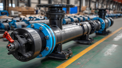
A quarter-turn usually moves the disc from open to closed. When the disc aligns with the flow, fluid passes through with limited resistance. When the disc rotates across the pipe, it blocks the passage. Operators may use a hand lever, gearbox, pneumatic actuator, or electric actuator. The valve body can sit between pipe flanges, which saves space and installation time.
Its basic purpose is simple: isolate equipment or regulate flow. For example, a technician may close the valve before cleaning a pump. In water systems, larger sizes are common because the compact design reduces weight. However, throttling can increase turbulence and wear. That detail is sometimes overlooked. The term “butter valve” itself is imperfect, and relying on it alone may cause specification errors. Material compatibility, pressure rating, temperature, and sealing performance must match the actual service. A careful installer verifies these points before operation.
What Is a Butterfly Valve and How Does It Work?
A butterfly valve uses a circular disc mounted on a rotating shaft to control fluid flow.
The disc normally turns through 90 degrees: at 0° it blocks the passage, while at 90° it is aligned with the flow path.
The chart shows the theoretical geometric opening reference based on the disc angle; actual flow capacity also depends on valve size, disc design, pressure, and fluid conditions.
Main Components and Their Functions
What Is a Butter Valve and How Does It Work?
Main Components and Their Functions
A butter valve, often called a butterfly valve, controls flow through a pipe. Its central disc rotates around a stem. When the disc turns parallel to the pipe, fluid passes through with limited resistance. Turning it across the passage blocks the flow. The mechanism is simple, but installation accuracy still matters.
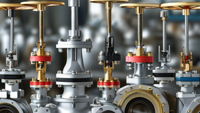
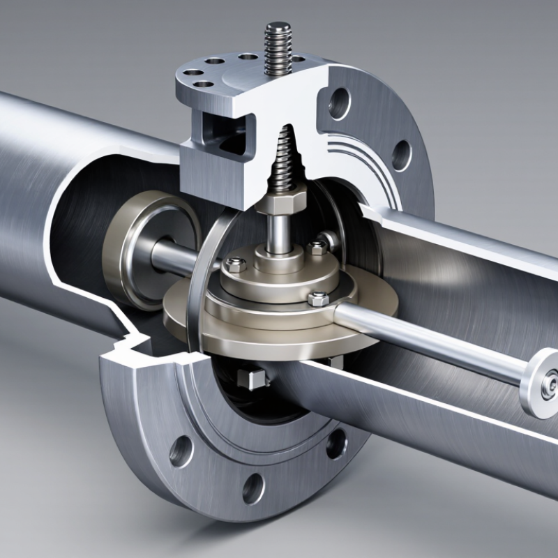
The valve body connects to the pipeline and supports the internal parts. Inside, the disc manages the opening area. The stem transfers movement from the handle or actuator to the disc. A resilient seat seals around the disc edge and helps prevent leakage. Some designs use metal seats for higher temperatures and tougher service conditions.
The actuator provides controlled movement. Manual handles suit smaller systems, while pneumatic or electric actuators support remote operation. Bearings guide the stem and reduce friction. Seals protect the stem area from unwanted leakage. A position indicator shows whether the disc is open, closed, or partly open.
During inspection, technicians should check the seat, stem, and flange alignment. Even a small misalignment can increase wear. Dirt may also prevent a full seal. No design is perfect. A valve can look closed while a damaged seat allows flow to continue. Testing under safe operating conditions remains essential.
How a Butter Valve Operates Step by Step
A butter valve, more accurately called a butterfly valve, controls flow with a circular disc. The disc sits across the pipe. Its shaft connects to a handle or actuator. In the open position, the disc turns parallel to the fluid. Resistance stays relatively low. In the closed position, it rotates 90 degrees and blocks the passage. Simple, but not foolproof.
Operation begins with a command from an operator or control system. The actuator turns the shaft. The shaft rotates the disc inside the valve body. As the disc moves, the opening changes and regulates flow. At the end of travel, the sealing edge presses against the seat. Correct alignment matters. A small installation error can cause leakage, vibration, or uneven wear.
UNESCO’s United Nations World Water Development Report 2024 states that agriculture accounts for about 70% of global freshwater withdrawals. In such systems, stable valve control matters. The U.S. Environmental Protection Agency’s 2023 drinking-water infrastructure survey estimates $625 billion in needs over 20 years. Maintenance cannot be an afterthought.
Tips:
Check the flow direction, shaft movement, and seat condition before commissioning. Move the valve slowly during testing. Watch pressure gauges and listen for chatter. Never assume a fully open valve has zero pressure loss. I have seen clean-looking valves fail because debris sat beneath the disc. That detail is easy to miss. Inspect it anyway.
Advantages, Limitations, and Maintenance Considerations
A butterfly valve, sometimes called a butter valve, controls flow with a circular disc mounted on a rotating stem. Turning the stem a quarter-turn moves the disc from parallel to perpendicular to the pipeline. This simple action makes the valve compact, lightweight, and quick to operate. The 2024 Industrial Valves Market report by Fortune Business Insights estimates continued market growth, driven partly by water treatment, energy, and process industries. That demand reflects a practical advantage: smaller valves reduce installation space and handling effort.
However, the design has limits. The disc remains inside the flow path, even when fully open, so it can create pressure loss and turbulence. Sealing performance also depends on correct material selection, temperature, pressure, and fluid compatibility. A resilient seat may work well in clean water but degrade faster with abrasive slurry or aggressive chemicals. Field experience matters here. A valve can look healthy outside while its seat is quietly hardening. Not obvious.
Maintenance should include visual checks, stem-operation tests, flange inspection, and torque monitoring. The U.S. Department of Energy reports that compressed-air leaks can waste substantial system energy, sometimes exceeding 20% of total compressor output; poorly sealed isolation valves can contribute to this loss. Operators should inspect leakage under normal operating pressure, not only during shutdowns. Cleaning the disc area, checking fasteners, and recording operating torque helps reveal gradual wear. Still, maintenance schedules should not be copied blindly. Actual cycling frequency, fluid cleanliness, vibration, and temperature should shape the interval.